On Radiance materials - Physics
On material modelling in Radiance
author: Dr. Peter Apian-Bennewitz, pab-opto
introduction,
getting materials into Radiance,
examples
Since you're reading this on the workshop CD: There's an updated version available at http://www.pab-opto.de/radiance/vortrag_september_2002 .
All in all, Radiance models the every-day experience with light in an efficient and field-tested way.
More specific, Radiance calculates light levels by simulating light transport from light emitting surfaces while taking into account
other light reflecting surfaces.
This text tries to put modelling of the surface properties in a general context and gives some examples.
Physics are described loosely, while avoiding to be incorrect. Check here
for a more complete discussion (currently in German).
Physics
Introduction
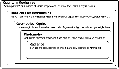
Electro-magnetic radiation with a wavelength between ~400nm and ~700nm stimulates receptors in the human eye and is called light.Radiance works within the concept of photometry, itself a part of geometrical optics, which is embedded into more general theories (diagram 1). It excludes diffracting phenomenona (e.g. light emitting surfaces and holes can be arbitrarily small without diffracting effects), coherence (how holograms work), polarisation (waves can oscillate in different ways) and non-linear optics (two photons together are more than the sum). Also material properties don't depend on the incoming radiation energy (e.g. they don't heat up and re-radiate).

Diagram 1: Radiance within current theoretic frameworks of optics
Units
Most general, the "thing" transported between surfaces by radiation is physically termed power, energy per second, it's unit being Watt. For radiative transport, the most practical value which is used everywhere is termed Radiance: Power per solid angle and emitting/receiving surface area, it's unit being Watt/sr.m2.If the direction of radiation is of no concern, the sum (more precisely the integral) over all incoming (or outgoing) directions for a receiving/emitting surface element is termed Irradiance, Watt/m2 .
Wavelength dependency sneaks into the concept since the human eye is not equally sensitive to visible radiation: 1Watt of red light doesn't like as bright as 1Watt of green light. So, for practical reasons, the unit of Lumen was defined, as the radiated power at a given wavelength multiplied by the standard human eye response at that wavelength. 1Lumen of red light looks as bright as 1Lumen of green light to the standard human observer. Units which use Lumen are called photometric, whereas units using Watt are called radiometric. The two most useful photometric units are termed Luminance: Nits=Lumen/sr.m2 and Illuminance: Lux=Lumen/m2 .
Standard Radiance cares for wavelength dependency by computing three channels in parallel, so every constant and input/output value is given as a triple. Typically these three channels are associated with three wavelength intervals vaguely described as red-green-blue. The exact wavelength intervals are up the user and have to be known to calculate the triples fed to Radiance as surface properties and for the interpretation of output triples. Internally, Radiance calculates "radiometric" and assumes specific wavelength association of the three channels only at interpretation of the results (e.g. when "falsecolor" or "ximage" are called). This text will ignore any specific wavelength dependency.
BRTF
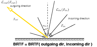
Power is assumed to travel along straight lines between surfaces, at which the incoming energy interacts with the surface properties and leaves the surface in various directions with various power. The space between surfaces is assumed to be empty, apart from possibly modeled volume scattering, which is not considered here.The surface properties are completely and generally described by the Bi-Directional-Reflectance-Transmission-Function (BRTF, also termed BRTD and some other four-letter-acronyms starting with B). Its mathematically sound definition is implicit, the incoming Radiance (symbol: L) is folded by the BRTF to give the outgoing Radiance:

Diagram 2: BRTF parameters
L(xin) and L(xout) are the incoming and outgoing Radiance. xin and xout specify the incoming/outgoing directions (given as normalized vectors or two angles ). dOmegain is the infinitesimal solid angle for each incoming direction, and the integral extends over the incoming hemisphere (or the full sphere if the BRTF includes both transmission and reflection).
Diagram 3: BRTF definition
While it seem counter-intuitive at first, this notation is of fundamental usefulness to describe and understand measurements, models and limits thereof.
Note that the BRTF is not limited to [0..1]. In fact any ideal specular surface is described by a Dirac Delta-function, which is zero except for a single point, at which it is infinity.
Energy conservation implies that the integral over all incoming directions of the BRTF must be less than 1 and geometrical optics enforce max(Lout)<=max(Lin).
Truly, the BRTF depends on a fifth parameter, the wavelength. As announced earlier, this text concentrates on the spatial properties of the BRTF and will not explicitly write out any wavelength dependency.
Since the BRTF is not a single number, it is not very well suited to describe materials in
brochures, sales documentation and labels. On the other hand, most materials used in architecture have either ideal specular BRTF
(incorporating all sorts of coated glass through which the outside can be clearly seen) or a smooth BRTF (Gaussian shaped, non-specular),
optionally plus a specular part.
So, for most common materials, it makes sense to boil the BRTF down to a single number per incident direction.
In common use are two values: direct-hemispherical reflection (rhodh) and direct-hemispherical transmission
(taudh).
For an incoming direction, the direct-hemispherical transmission is the integral of the BRTF over the outgoing hemisphere:
(rhodh is defined the same way)
taudh and rhodh values are limited to [0..1] .
Diagram 4: taudh definition
If not explicitly stated, the values are typically measured for an incident direction normal to the surface (transmission) or for alphain=8o (reflection).
Last modified Monday September 02, 2002
