Example: Writing a Radiance "cal" file
Scene files: cal-example-scene.zip

|

|
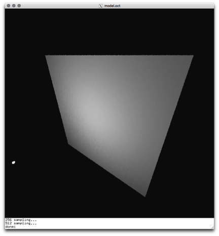
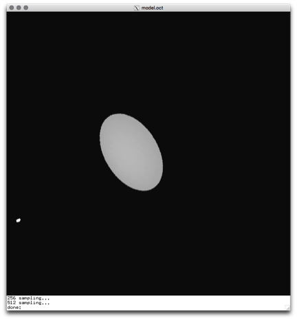
| An illuminance view showing the light distribution and the shape of the polygon. Light is received by the entire surface. | The luminance image of the same scene, showing the light cut-off on the polygon surface: whenever the light hits the material at an angle higher than the one set (25º in the example), the luminance is 0 and thus the image black. |
Overview
First, I suggest you read the father of all the cal files: rayinit.cal. It may be found in the Radiance lib directory. Here you can familiarize yourself with the cal syntax. A comment at the head of the file gives the names of the predefined symbols. For instance, the surface normal vector is [Nx, Ny, Nz], a point is [Px, Py, Pz], and so on.
Some materials accept light ray direction vectors as input. As this example shows, the names are up to you. The example uses x, y, and z, but k, j,y or ss, rr, and tt could also be used.
The cal file shown here defines a material that has a non-zero reflectance only when the light falling on the surface has a single incident angle. This property might be useful in testing a shading system over a facade or building envelope; try it out.
Code
Save as test.cal:
{multiply radians by conv to get degrees}
conv = (180/3.141592654);
{L = [x y z] is the light ray vector}
{N = [Nx Ny Nz] is the normal to the surface}

{normal vectors in the horizontal plane}
nl(x,y,z)=(x^2+y^2)^0.5;
nn=(Nx^2+Ny^2)^0.5;

{horizontal angle N - Lh}
cosa(x,y,z) = (x*Nx+y*Ny)/(nl(x,y,z)*nn);
hor(x,y,z) = conv * Acos(cosa(x,y,z));

{vertical angle N - Lv}
tanb(x,y,z) = z/(nl(x,y,z)*cosa(x,y,z));
ver(x,y,z) = conv * atan(tanb(x,y,z));

{angle N - L}
ang(x,y,z) = conv * Acos(x*Nx+y*Ny+z*Nz);

{now specify the cut off}
{cutoff: light is allowed if the angle is greater than the cutoff; blocked if it is less}
cutoff = 25;

{here the cut off is an angle of a cylinder in P}
testa(x,y,z)= if(cutoff-abs(ang(x,y,z)),1/(abs(x*Nx+y*Ny+z*Nz)),0);

{here the cut off is an angle between           }
{the normal and a line in the horizontal plane}
testh(x,y,z)= if(cutoff-abs(hor(x,y,z)),1/(abs(x*Nx+y*Ny+z*Nz)),0);

{here the cut off is an angle between the}
{normal and a line in the vertical plane   }
testv(x,y,z)= if(cutoff-abs(ver(x,y,z)),1/(abs(x*Nx+y*Ny+z*Nz)),0);
To test the cal file, this model file will do:
void plasfunc test
 2 testa test.cal
 0
 4 0 0 0 1

 test polygon vert
 0
 0
 12
 -1 0 -1
 1 0 -1
 1 0 1
 -1 0 1
 void light light
 0
 0
 3 23.349 23.349 23.349

 light sphere source
 0
 0
 4 0 -1 .2 .01
